01. Getting started with PUMOTIX CAM
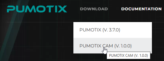
1. Download and install the program from the website pumotix.com.
To do this, hover your mouse over the download button and select PUMOTIX CAM. The program will start downloading automatically.
Install the program, step by step
 →
→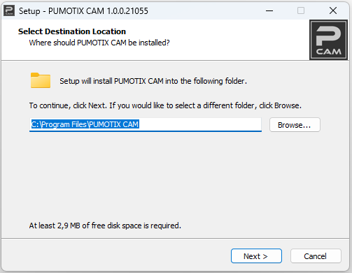 →
→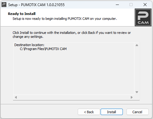 →
→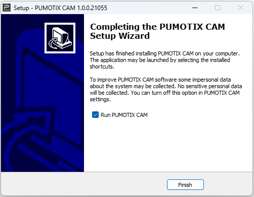
After installation is complete, the program shortcut will appear on your desktop. Run the program and wait for it to load.

2. Features available at first launch.
After launching the program, let's study its capabilities. Without an active license, you can perform the following actions:
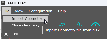
- Import one DXF file.
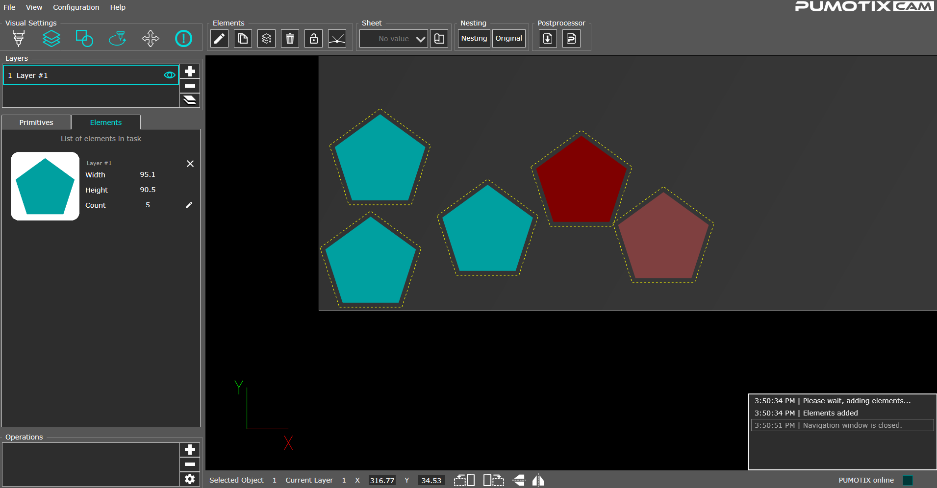
- Adding basic elements from the library (rectangle, line, polygon, and circle).

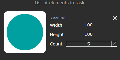
- Editing the quantity of parts by changing the “Count” setting, as well as duplicating and deleting selected elements.
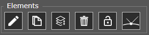
- Button “Block element actions” allows you to lock the current layout to make further changes.
- Кнопка "Переноса точки врезания" позволяет перенести точку врезания(что бы кнопка была активна должна быть настроена траектория).
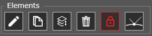
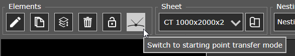 После нажатия на кнопку она подсветится (как на фото), что говорит о переходе в режим редактирования точки врезания. При наведении на траекторию, появиться возможность перенести точку врезания, что бы подтвердить место новой точки врезания нажимаем левой кнопкой мыши. Для того чтобы выйти из режима редактирования врезания, необходимо снова нажать на кнопку.
 →
→
- Кнопка "Редактировать выбранные элементы" позволяет изменять параметры размещённых элементов: положение, масштаб и поворот.

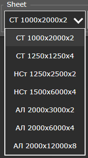
- Selecting the size and type of sheet, using the built-in library and the ability to edit it.


- Manual placement allows you to move parts around the sheet. This function takes into account the different number of selected parts, as well as the correctness of the layout (when the trajectories intersect, the parts are highlighted in red).
- Changing the layout density in the menu “Configuration” → “Settings” → “Nesting”. The parameter set minimum distance between elements.

- Filling in the tool library.

- Adding operation.

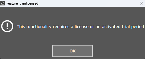
If you don't have a permit for some operation, the program will notify you about it.
3. Connecting the controller, activation trials.
To access the full functionality, you need to link PUMOTIX CAM with your existing PLCM controller. To do this:
- download and install the latest version of PUMOTIX CNC 3.7.0 from the website (direct link to download the archive with the software);
- run PUMOTIX CNC and select PLCM controller from the list. Wait for the device firmware to be updated.
Select in the menu “Configuration” → “Settings”. On general tab you can see the list of devices. Select the controller that was updated in PUMOTIX in the previous step.

For full use, use trials by activating them in the “License Manager” (menu item “Configuration”). If you needed feature, you can always purchase them on our website (www.pumotix.ru).

4. Creating G Code.
In order to download the control program to a file or send it to the CNC system, the “Using CAM basic functions” option is required.
Main feature, PUMOTIX CAM — it is fully integrated with PUMOTIX, which allows you to open the program directly in the CNC system with just a few clicks. This reduces the number of unnecessary files and greatly speeds up the workflow.
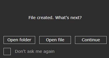
The capabilities in PUMOTIX CAM allow you to generate a file and select actions after post-processing:
- open file;
- open folder;
- continue.
All additional post processor settings (e.g., the path to save the file, set the file name) you can find in menu “Configuration” → “Settings” → “G Code”.

5. Additional examples of using full functionality, PUMOTIX CAM.
Each option introduced expands the functionality of the program for more convenient and complete use.
For example, the activated option “Extended built-in library of standard parts” allows you to use more complex parts, such as a bearing, a star, a frame, etc. All basic elements contain a set of editable parameters.

Another example would be the “Simple auto nesting”, which activates the “Nesting” button on the main screen, allowing parts to be nested automatically based on the specified sheet dimensions.

Also pay attention to the notification window, which even when minimized will not allow you to miss system information. The window opening icon reflects the number of unviewed messages if the window was closed for some reason.

6. If you still have questions or any problems…
You can use “Help” → “Technical support request”, generate a report with diagnostic information and send it by email to support@pumotix.ru with a detailed description of the issue.

Learn more about how to generate and submit a report: “PUMOTIX CAM Diagnostic Information Report”