Controlled rollgang settings
The PUMOTIX feature allows you to configure one or more motors to control the rollgang.
Make sure that you have access to a license to control the rollgang before setting up. You can check the availability of a license for a feature in the menu "Configuration" → "License Manager". Expand the "General Features" node in the PUMOTIX features tree. You can use the trial period if the "Controlled rollgang support" feature is not activated.
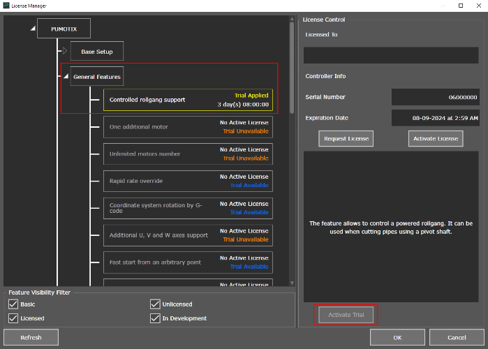
Activation of the trial period of the "Controlled rollgang support" feature
As an example, consider the setup of a pipe cutting machine with a rollgang, working in tandem with a rotary axis B.
Go to the menu item "Configuration" → "Settings" → "Motors" to start configuring.
The following figure shows an example of setting up motors for a pipe cutter mounted along the Y axis of the machine. The pipe cutter is controlled by two independent motors: one rotates the chuck, the other rotates the rollgang.
For the convenience of further configuration, we will rename the rotary axis motors to “Chuck” and “Rollgang”.
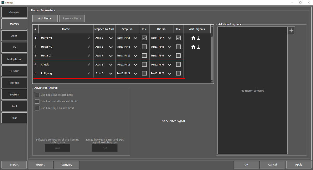
Motors Settings
You need to go to the “Axes” settings tab after setting up the motors. Select the rotary axis from the drop-down list at the top of the window. In this example we use the B axis.
Make sure that basic axis parameters, such as movement parameters, are configured.
Let's move on to setting advanced motor parameters for the rollgang when the basic characteristics of the axis have been configured. To do this, in the right part of the axes settings window, turn to the “Additional features” block.
From the drop-down list you must select the motor that is connected to the rollgang.
Check the "Motor as Rollgang" option to "tell" the system that this motor is part of the rollgang.
The basic idea of automatic rollgang control in PUMOTIX is the following points:
- There is only one rotary axis (A or B), but there can be several motors attached to the rotary axis (for example, a chuck and a rollgang).
- The speed F and moving distance (for example, G0 B720) are set for the rotary axis, not for the rollgang motor.
- The rollgang rotation speed should be calculated automatically based on three parameters:
- rollgang roller diameter;
- count of STEP pulses to rotate the roller by 1 degree;
- diameter of the pipe installed on the rollgang.
In order for the system to automatically calculate a correction factor for relating the pipe diameter to the roller rotation speed, the following data must be entered into the system settings:
- Diameter of the rollgang roller (in mm or inches).
- Count of STEP pulses to rotate the roller by 1 degree.
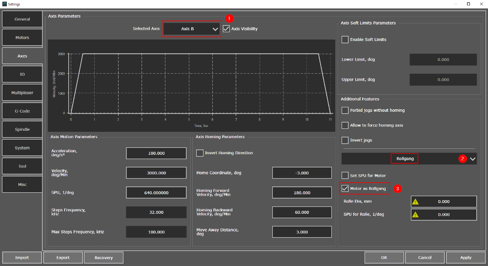
Axes Settings
Enter the missing values in the rollgang settings and click the "Apply" button in the lower right corner of the settings window.
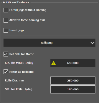
Advanced settings for the rollgang
Please note that the option "Set SPU for Motor" is automatically activated. The STEP value field has become read-only in this case. The yellow triangle icon warns us that the value of the count of STEP pulses for the rollgang motor will be automatically calculated based on the specified parameters of the rollgang and pipe diameter. We will move on to setting the pipe diameter later.
Now this motor is defined to control the roller table, as evidenced by the icon that appears in the “Motors” tab.
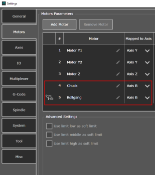
Rollgang motor display
At this stage, the settings of the motors and axes can be completed.
It is necessary to determine the diameter of the pipe that will be used for processing to test run a rotary axis with a driven roller conveyor.
The pipe diameter in PUMOTIX plasma and oxy-fuel cutting modules can be set in two ways:
- From the PUMOTIX GUI. The parameter input field is located on the "Process parameters" From the PUMOTIX GUI. The parameter input field is located on the "Process parameters" tab → "Pipe diameter".
- Using a special M-code with a parameter. For example, M94 P400 (where 400 is the pipe diameter).

To prepare NC program in SheetCam THG, it is recommended to use a specialized post-processor:
To select this postprocessor in SheetCam, go to Settings → Machine Settings → Postprocessor → Import post and specify the path to the file.
To unload a NC using this postprocessor, you must specify the pipe diameter. To do this, in the list of operations, click the Set post variable button, from the variable name drop-down list, select the diameter variable and specify the value of the outer diameter of the pipe.
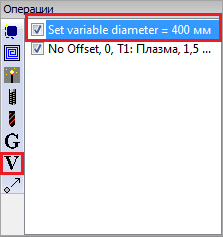
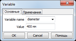
The M94 P400 command will be added to the generated NC by the postprocessor, informing the PUMOTIX CNC system of the used pipe diameter.

If the Pipe Diameter parameter does not satisfy the specified restrictions, the use of the rotary axis for which the rollgang is configured will be unavailable both from the NC and in the manual movement mode, with the corresponding warning being displayed.
Congratulations, we have configured the motor to control the drive roller table. You can start working!
