Supported Trajectory Modes
The PUMOTIX system supports several different driving modes along a given path. Each of the modes is a compromise between the execution speed of the G-Code and the accuracy of following a given trajectory. These processing modes are switched by the G-codes considered below.
G61, G61.1: Exact stop
G61.1: Accurate movement with a stop after each line of the G-Code. This mode is the most accurate, but the movement is extremely inefficient.
G61: Exactly following the trajectory at the highest possible speed. It differs from the previous mode in that for each common point of two adjacent G-Code lines, the maximum allowable speed is calculated in advance so that the specified acceleration is not exceeded for any axis.
For example, if the following code block is encountered in a unitary enterprise:
G91 G61 F1500
G1 X5
G1 X5
then the movement of 10 mm will be performed as a single unit, since it is obvious that two segments can be performed as one. The speed graph for the execution of this G-code is shown in the figure below.
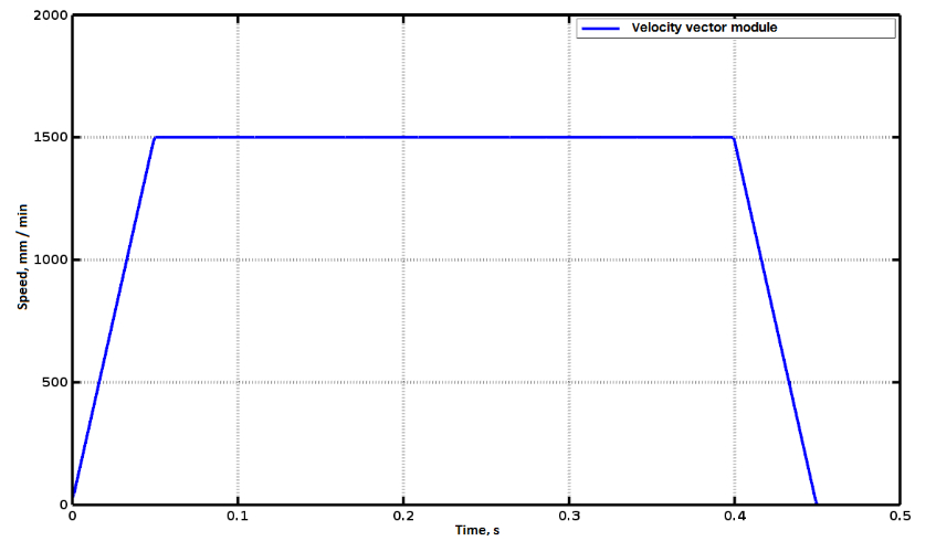
Graph of the tool linear velocity module in G61 mode
If in the example, replace G61 with G61.1 then two movements will be performed separately with a stop at an intermediate point.
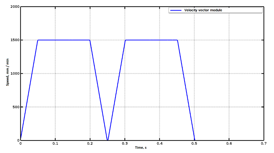
Graph of the tool linear velocity module in G61.1 mode
Consider a more complex case:
G90 G61 F1500
G0 X0 Y0
G1 X10
G1 X20 Y0.1
Here at point (10.0) the trajectory turns a bit, there is a small angle. In order to unambiguously answer whether it is necessary to slow down the speed at the turning point or not, it is necessary to know the exact parameters of the system, namely the permissible speeds and accelerations for the X and Y axes, as well as the current feed F. During execution of the G-Code all these parameters are known to the system, and the maximum speed of each corner is calculated automatically. Below is a graph of the speed when executing this code with maximum accelerations along the axes of 500 mm/s2.
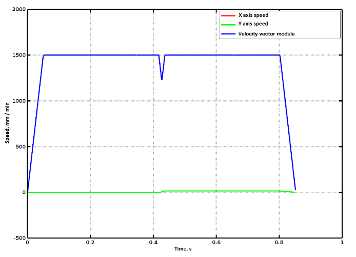
Graph of linear tool speed in G61 mode with rotation on the path
G64: Constant velocity with a given error
When you enable this mode, you must specify a tolerance other than zero, for example, 0.1 mm: G64 P0.1. Setting the zero value is equivalent to the exact path mode (G61). G64 is the fastest execution mode for G-Code.
When this mode is turned on, the system rounds the path in such a way that the permissible deviation of the real tool path from the path specified in the G-code does not exceed the value P. This avoids sharp corners and, as a result, increases the permissible speed of the junction points of adjacent code lines.
Consider an example:
G90 G61 F1000
G0 X0 Y0
G1 Y5
G1 X5
G1 X0 Y0
G64 P0.5
G1 Y5
G1 X5
G1 X0 Y0
G0 X0 Y4.5
G3 X0.5 Y5 I0 J0.5
G0 X5 Y4.5
G2 X4.5 Y5 I0 J0.5
In this code, two identical movements along the triangle are performed (0,0) → (0,5) → (5,5) → (0,0).
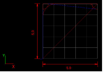
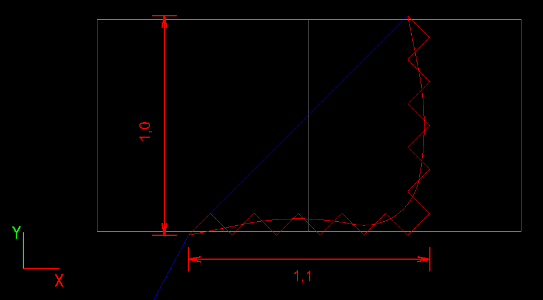
Example toolpath in modes G61 and G64 P0.5
But in the first case, the movement is performed in G61 mode, and we see a triangle with sharp corners in the trajectory window, as expected. Next, the G61 P0.5 mode is activated, which means the inclusion of smoothing with a tolerance of 0.5 mm. Accordingly, the second triangle has smoothed corners.
At the end of the G-Code, two arcs are drawn with centers at the vertices of the triangle and a radius of 0.5 mm. It can be clearly seen in the screenshot that the angles of the triangle were smoothed with a deviation from the exact G-Code of no more than 0.5 mm.
The following figure shows the speed graph when executing the UP from the example above.
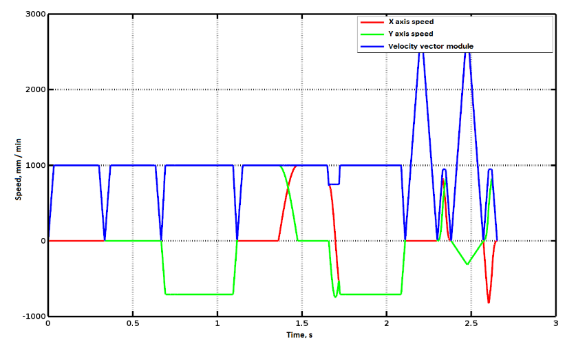
Comparative speed graph in G61 and G64 modes
The first three blue trapezoid on the graph is the speed of movement on the three sides of the triangle in G61 mode.
It is clearly seen that at the end of all three segments the speed drops to zero, since the corners are too sharp and they cannot be passed without braking without violating the specified accelerations.
Starting from 1.1 s, the G-Code is repeated, but in smoothing mode. The graph clearly shows that from the beginning to the level of 1.4 s only the Y axis moved (the vertical side of the triangle), then the Y axis smoothly brakes and X simultaneously accelerates, while the resulting speed remains constant - 1000 mm/min. However, the acute angle of the triangle could not be passed without speed reduction, despite its rounding. The fact is that the radius of the circle is too small and if it is passed at a speed of 1000 mm/min, the centripetal acceleration will be higher than the permissible (500 mm/s2 in this experiment). Therefore, the system reduced the speed to the maximum permissible.
Note that only those movements that occur in the main coordinate system XYZ are smoothed out. If there is movement along the auxiliary axes ABC or UVW in the G-Code block, then this trajectory will not be smoothed, that is, G61 mode is temporarily implicitly turned on for it.
In addition, only the angles formed by two segments G1are subject to rounding. Arcs are not smoothed, since they are already smooth curves and, as a rule, if they are present in the code, then they are already smoothing elements. G0
is not smoothed out, since it is more of a transfer for official use, and not part of the material processing.
Despite the fact that the above examples consider the movement in the plane, the rounding of the corners is carried out simultaneously along all three XYZ axes.
The described modes can be alternated inside the G-code. Moreover, sometimes it may be necessary. For example, if you want to specify that a certain command cannot be smoothed. This may be, for example, the operation of lowering the cutter into the material along the Z axis:
G64 P0.5
….
G0 X0 Y0 Z5
G61
G1 Z-1 F100
G64 P0.5
G1 X100 Y100 F1000
If you delete the line G61 from the example above, then at the end of lowering the Z axis, the system will begin to round the path towards the next movement along the X, Y axes, which can lead to breakage of the cutter.
In G64 mode, it is possible that some paths are shorter than the smoothing tolerance.
Comparison of toolpaths in modes G61 and G64 P0.5
In the example, the same G-Code fragment is executed twice again in the G61 and G64 P0.5 modes.
It is seen that when trying to smooth this trajectory, some segments were combined into larger sections, however, the total error still does not exceed 0.5 mm.