What is the "Tool Table" for?
Filling the tool table
The “Tool Table” can be found through the path "Configuration" → "Tool Table". Below is the appearance of an empty tool table.
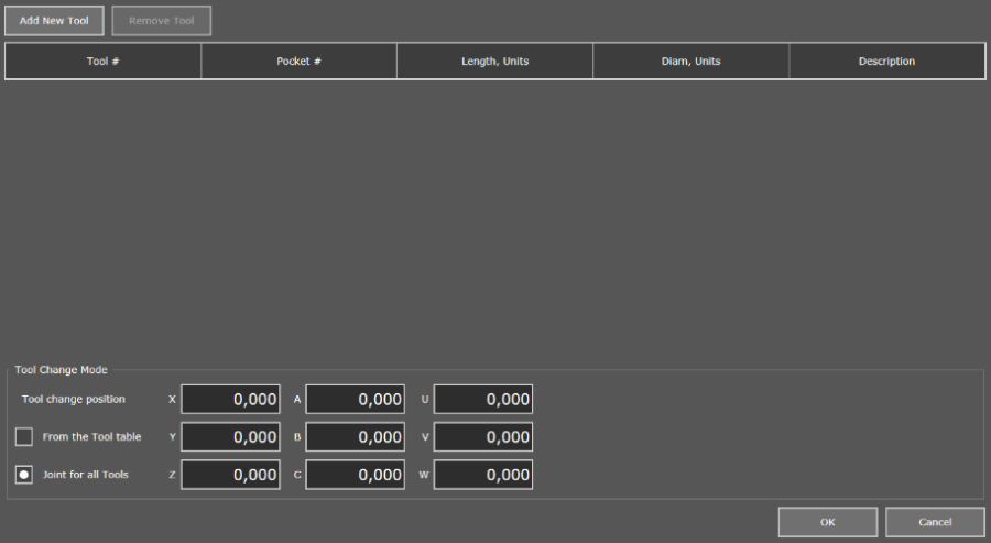
In the upper left part of the window, click the "Add New Tool" button to add a new tool to the table. By default, the tool number and cell number are assigned to the new element, and the length and diameter values are zero. Only the first two columns of the tool description are required, the rest can be zero or empty.
In the lower left part of the window is a field that allows you to select the tool change mode. By default, the tool change position "Joint for all Tools" is selected, and the coordinates of the change point are zero. Changing the coordinates must be done right here then during the operation of the macro M6 the spindle will move to the specified point.
The user gets the opportunity to set the coordinates of the change point for each tool in the table when choosing a shift position "From the Tool table".
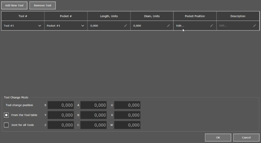
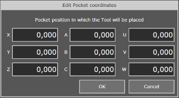
In the "Pocket Position" column, click "Edit..." so that the window for entering the coordinates of the tool change point appears.
A fully filled table has the following form (example):
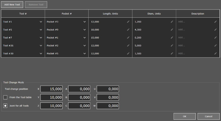
After filling out the table, click "OK" to apply the changes.
Now, when the tool change command (M6) is called in the G-code and the tool number is indicated (Tx, where x is the tool number from the table), the number and parameters of the tool that was selected will be displayed on the "Workflow Process" tab.
In which cases is the diameter of the tool taken into account?
To take into account the tool diameter indicated in the "Tool Table", it is necessary to add a special command to the control program (G40, G41, G42) after the change command with the tool number (M6 Tx, where x is the tool number from the table) or with the declaration of the tool number in the G-code (Tx). This procedure is called Tool Compensation.
The command’s job is to adjust the trajectory taking into account the diameter of the tool so that the final result matches the original task and does not have to redo the tool every time you have to change the cutting tool. The program automatically changes the cutting path depending on the selected compensation mode (more...). A good example of the command operation can be seen in the visualization window of the PUMOTIX program.
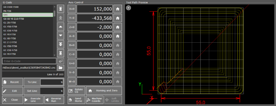
Trajectory G-Code taking into account the diameter of the tool
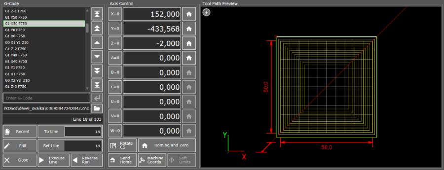
G Code trajectory without tool diameter
When is the value from the Length field applied?
The value of the "Length" field from the tool table is taken into account when automatically changing the tool to adjust thespindle height. Read more on the page "How to Work with Tool Change?"