Motors Setup
The concept “Motor” includes such concepts as Step/Dir/Enable outputs, home (zero) sensors, axis boundary sensors, as well as the axis to which this motor is attached. Adding a new motor and setting parameters is carried out on the “Motors” tab.
PUMOTIX allows you to configure the following motor parameters:
- Main parameters:
- Motor name;
- Mapped axis;
- Step output;
- Dir output.
- Additional parameters:
- Enable output;
- Home input;
- Limit Low input;
- Limit Middle input;
- Limit High input.
- Advanced parameters:
- using limits as soft limits;
- software connection of the homing switch;
- delay between STEP and DIR signal switching.
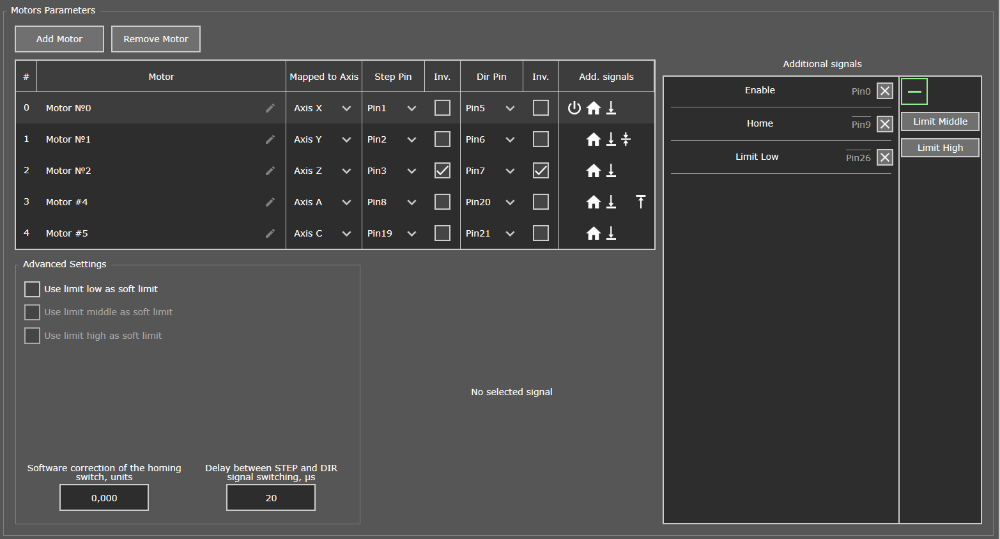
“Motors” Tab
Main parameters
The main parameters of the motor are those parameters without setting which it is impossible to work. The main parameters are in the table in the upper left part of the window. Use the buttons above the table with the main parameters to add and remove motors.
Motor
The machine operator can set any intuitive name for the custom motor. By default, this parameter has the value: motor, ID = N, where N is the motor serial number, starting from zero. The motor can be set to any name, for example, the X-axis motor or the Y-axis motor (left), etc.
Mapped Axis
motors can be attached to axis. All motors assigned to the axis will carry out movements with the same parameters of steps per uint (SPU) , speed and acceleration specified on the “Axes” tab. For more information about homing, see the Axes setup section.
Step output
The number of the output pin (or port and pin for multiport controllers) to which the Step control signal will be generated for the driver of this motor. STEP signal - a clock signal, a step signal. The Step signal level can be inverted by checking the corresponding box in the Inv.
Dir output
The number of the output pin (or port and pin for multiport controllers) to which the Dir control signal for the driver of this motor will be generated. The Dir signal is a potential signal, a directional signal. The signal level Dir can be inverted by checking the corresponding box in the Inv.
Below is an example of tuned motors for 5 axes. The settings table has additional columns, for example the engine number or the display of the configured additional parameters.
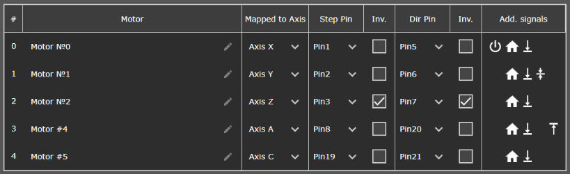
Example of setting the main motor parameters
Additional parameters
Additional parameters are not required for settings, but they are necessary for optimal motor performance. Some additional parameters can be configured only for a CNC machine of a certain configuration. The selection of additional parameters is in the right part of the window.
Enable output
The number of the output pin (or port and pin for multiport controllers) to which the Enable control signal will be sent - a potential signal, a driver on/off signal. The signal level Enable can be inverted by setting the corresponding checkmark in the Inv.
Home input
The number of the input pin (or port and pin for multiport controllers) to which the signal from the home (zero) axis sensor for this motor will be supplied. When using two or more motors on one axis of the portal, make sure that each motor of this axis has its own base sensor. Otherwise, the skew or jamming of the portal is possible. The signal level Home can be inverted by checking the corresponding box in the Inv. In the absence of home sensors, this parameter is not configured. More details about the homing are described in the Axes settings section and in the article.
Limit Low input
The number of the input pin (or port and pin for multiport controllers) to which the signal of the sensor for the lowest axis position (lower limit sensor) for this motor will be supplied. When using two or more motors on one axis of the portal, make sure that each motor of this axis has its own low position sensor. Otherwise, a mechanical shock of the portal into the machine bed is possible when the axis is moved to its lowest position. If the sensor is active, it is allowed to move in positive direction only. The signal level Limit Low can be inverted by setting the corresponding checkmark in the Inv. In the absence of lower boundary sensors, this parameter is not adjustable.
Limit Middle input
The number of the input pin (or port and pin for multiport controllers) to which the signal of the sensor for the middle axis position (middle limit sensor) for this motor will be supplied. The signal allows you to separate two machine zones, such as the table zone and the rotary axis zone. When the signal is triggered, the system automatically switches to emergency stop mode. If the sensor is active, it is allowed to move in both directions. The signal level can be inverted by setting the corresponding checkmark in the Inv.
Limit High input
The number of the input pin (or port and pin for multi-port controllers) to which the signal of the sensor of the highest axial position (upper limit sensor) for this motor will be supplied. When using two or more motors on one axis of the portal, make sure that each motor of this axis has its own upper position sensor. Otherwise, a mechanical impact of the portal into the machine bed is possible when the axis is moved to its highest position. If the sensor is active, it is allowed to move in negative direction only. The signal level Limit High can be inverted by setting the corresponding checkmark in the Inv. In the absence of upper boundary sensors, this parameter is not adjustable.
Below is an example of setting additional motor parameters. Next to the parameter name you can see the number of the configured pin and its inverse.
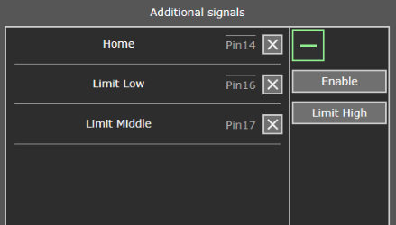
Example of setting the additional motor parameters
Advanced parameters
The advanced parameters are optional. Advanced parameters include soft limits for low, middle and high limit, software connection of the homing switch and the delay between STEP and DIR signal switching.
Using limits as soft limits
Using soft limits allows you to stop the current motor without switching to E-stop. This limits further movement towards the sensor. It is possible to set any limit as soft limit.
Software connection of the homing switch, units
The parameter sets the software offset of the homing sensor and can be used to eliminate the skew of the portal axes.
Delay between STEP and DIR signal switching, ms
This parameter sets the delay between the STEP signal and the switching of the DIR signal. The choice of value may depend on the model of the motor driver used.
Below is an example of setting advanced motor parameters. Please note that these settings are optional.
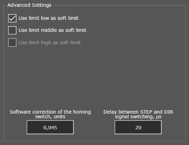
Example of setting the additional motor parameters
After motors settings it is recommended to proceed to settings the axes (see the Axes Settings section).