Axes Setup
Axes set the basic parameters of movements, homing parameters and limits of the CNC machine. Axes parameters are set on the "Axes" tab.
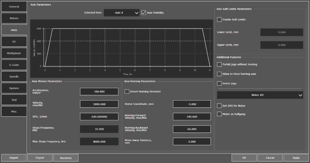
"Axes" tab
Axes settings have three main categories of parameters in PUMOTIX:
- movement parameters;
- homing parameters;
- parameters of soft limits.
Movement parameters
Acceleration, units/s2
It's a vector physical quantity numerically equal to the change in velocity per unit time. This parameter sets the maximum acceleration along the axis in units/s2.
Speed, units/min
It's a vector physical quantity equal to the ratio of displacement to the period of time during which this displacement has occurred. This parameter sets the maximum permissible axis velocity, expressed in units/min.
Count of Step signals, 1/unit
This parameter sets the number of Step pulses that must be generated to move the tool 1 unit distance (1mm, 1 inch, etc.). The parameter depends on the mechanics and on the step division mode set on the driver (for systems built using step drives), the electronic reduction coefficient and encoder resolution (for systems built using servo drives).
Step signal frequency, kHz
It is an axis parameter inaccessible for editing. Parameter depends on the set parameters of speed and count of Step signals. It displays the current frequency of Step signal generation. Please note that this parameter must not exceed the maximum Step signal frequency.
Maximum Step signal frequency, kHz
It is an axis parameter inaccessible for editing. Parameter displays the maximum possible Step signal generation frequency for the selected controller. For PLCM series motion controllers, the maximum generation frequency of Step signal is 100 kHz per axis.
Homing parameters
The home of the CNC machine (or absolute zero) is a fixed position of the machine. Usually this point is physically determined using special sensors installed on the CNC machine. Relative to this point the CNC system positions its absolute (machine) zero, or the origin of the machine coordinate system. In the future, the offsets for floating (working) zeros are set in this coordinate system. Absolute zero is uniquely tied to the mechanics of the CNC machine. Therefore relative movements are made related absolute zero to the design features of the machine. For example, entering the zone for automatic tool change, setting the Soft Limits (dimensional restrictions) of the machine, etc. (more about homing...)
Invert Search Direction feature
The option sets the axis direction to the sensor when homing do. It is necessary to change the state of this option to the opposite if the axis travels in the opposite direction from the sensor when starting the homing procedure.
Home coordinates, units
The home coordinate set in this parameter. It is the coordinate of the zero sensor (base sensor) of the axis in the machine coordinate system. The default value is 0 units (the origin of the machine coordinate system coincides with the base).
The system shifts the machine zero by the set value relative to the base sensor when setting the non-zero value of the current parameter.
The home (sensor trigger point) does not have to coincide with machine zero. We recommended that the base is not equal the origin. So the probability of triggering the home sensors is eliminated when executing the "return to machine zero" command.
For example, home coordinate is set -50 units for the X axis. When performing the homing procedure, the system will set the value of the machine coordinate to -50 moving out of the sensor along the X axis. Therefore, the current position will now have a coordinate of -50 which is the home for the X axis. The X axis will move to the coordinate X mach = 0 during the operation “Go to Machine Zero”. There will be no return directly to the sensor. This parameter, for example, can be used to offset the initial position of the machine coordinate system if the base sensors are not at the edges of the portal movement zone.
Sensor search speed, units/min
It is the speed which the system will move the current axis towards the home sensor. You must set the value of the search speed with the opposite sign to change the search direction of the sensor along the axis.
Sensor exit speed, units/min
It is the speed which the system will move the current axis when it moving out of the home sensor. This parameter is set to zero if there is no need to exit the sensor. The direction of the exit is determined by the system automatically depending on the direction of homing. Therefore, there is no need to explicitly indicate the sign (+ or -) for this parameter.
Exit distance, units
It is the distance the axis should move immediately after exiting the home sensor. Always performed towards the exit. Default value: 0 units (stop immediately after taking the signal from the sensor). This parameter is especially useful when it is necessary to eliminate false alarms of sensors. An example can be the case when one sensor is used both to search for bases and as a sensor of the axis soft limit position. The sensor will switch to the boundary position sensor mode immediately after the base search operation is completed in this case, and its short-term triggering (bounce) is possible in the immediate vicinity of the sensor. You can use one home sensor both to homing and as a sensor of the upper (lower) axis limit at the same time by setting a non-zero value for this parameter.
Parameters of Soft Limits
Enable Soft Limits feature
The feature allows you to set the lower and upper limits for the selected axis.
Lower Limit, units
It is the minimum value of the machine coordinate which the system is allowed to move along this axis. The lower limit value must always be less than the upper limit value.
Upper Limit, units
It is the maximum value of the machine coordinate which the system is allowed to move along this axis. The upper limit value must always be greater than the lower limit value.
It becomes possible to enable the function Soft Limits after setting the upper and lower limits and searching for absolute zeros (home) of the CNC machine.
Additional Features
Additional features binding allows you to rename axis, to establish a correspondence between the logical concept of "axis" and the executive elements of the system - motors, also to set the STEP value for the motor or to define the motor as a controlled rollgang. One motor can only be binding to one axis at a time. One axis can control several motors in this case.
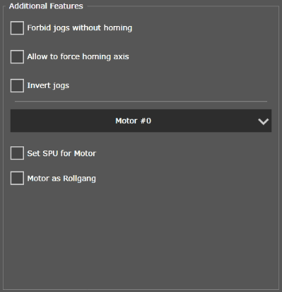
Additional Features
The binding is carried out in the same way with the indication of the combined motors if the system involves combining several motors in one axis. All previous links with other axes for this motor are canceled when linking the motor with an axis. Similarly, you can perform the linking of axes and motors on the "Motors" tab, setting the controlled axis for each of the motors.
PUMOTIX supports 9 axes configuration. Axes can be divided into three groups:
- Linear main - X, Y, Z
They carry out linear motion in three mutually perpendicular directions. The movement distance is interpreted in millimeters or inches, depending on the current settings. The speed is interpreted in mm/min or inch/min. Acceleration - mm/s2 or inch/s2. - Turnable - A, B, C
They carry out angular motion (rotation). Typically, axis A rotates around a line parallel to X. Axis B rotates around a line parallel to Y. Axis C rotates around a line parallel to Z. The movement distance is interpreted in degrees. The speed is interpreted in deg/min. Acceleration - deg/s2. The setting of "Count of STEP signals" is calculated so that the corresponding rotary axis performs exactly one revolution when a 360-degree rotation command is issued. - Linear optional - U, V, W
They carry out linear motion in three mutually perpendicular directions. Typically, axis X and axis U are parallel. Axis Y and axis V are parallel. And axis Z and axis W are parallel. The movement distance is interpreted in millimeters or inches, depending on the current settings. The speed is interpreted in mm/min or inch/min. Acceleration - mm/s2 or inch/s2.
Any CNC system has at least one axis. Different types of CNC machines have different combinations of axes. For example, a 4-axis milling machine may have an XYZA or XYZB axes. The lathe usually has an XZ configuration. A foamplastic cutting machine typically has an XYUV axes. Systems with two or more motors on the same axis is a gantry machines. An example is a portal milling three-coordinate machine with an XYZ-axes configuration, with two motors attached to the Y-axis installed along the edges of the portal.
PUMOTIX in the PLCM-E1b controller supports simultaneous control of four motors. The PLCM-E3 / E3p controller supports six motors. The count of motors is limited to six due to the hardware capabilities of the current generation of PLCM controllers.