Visualization of rotary axes
PUMOTIX, as of version 3.7.0.24269, supports visualization of rotary axes (configuration: rotary table).
You need to add a motor(s) and select the appropriate axis name (A, B, C) for each added motor to control rotary axes, and also configure the axis parameters in accordance with the driver settings.

Purpose of motors for the rotary axis
The visualization will automatically display rotary axes if it encounters rotary axes control in the loaded G-code. Three-axis G-codes will be displayed as before.

Rotary G-code display example
Each of the configured rotary axes by default has a rotation axis relative to the basic linear ones:
- A axis around X axis;
- B axis around Y axis;
- C axis around Z axis.
If the standard binding of the rotation axis does not correspond to the configuration of your machine, you can customize the binding for yourself using the "System" settings tab, the fields for binding the rotary axes.
It is also possible to configure axis inversion (checkbox next to axis selection). This option inverts the direction of the rotation axis and allows for finer adjustments to the final display.
Visualization may not display correctly for CNC-machines with "rotation head" configuration. So you can disable the display of rotary axes by unchecking the function "Show trajectory taking into account rotary axes".

Setting up rotation axes binding
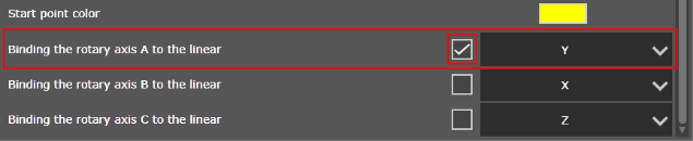
Enabling inversion

Disable rotating visualization