How to Work with Tool Change?
A tool change in the control program is called using the macro M6 with or without Tx parameter (where x is the tool number).
The PUMOTIX software provides users with the ability to change tools according to one of the 4 proposed scenarios.
Scenario 0: Default - installed in the program by default.
The call of the tool change command in the control program is ignored without notifying the user.
To use the tool change macro, go to “Configuration” → “Settings” → “G-code” → “G-code Interpretation Params” and uncheck the box “Ignore tool change”. Then click the “Apply” button and close the settings window.

The scenarios described below are implemented using various configurations of the M6 macro.
To apply the desired configuration select the M6 macro template (Auto or Semiauto) using the macro and background operation window.

Scenario 1: Pause control program.
This scenario is embedded in the standard macro M6 and will be executed without additional changes. When the toolchange command is called from the control unit, the spindle rises to the SafeZ height, stops rotation and remains in place,allowing any changes to be made, including additional measurements to correct coordinates in the program.
Scenario 2: Semi-automatic tool chan (the macro template is the SemiAuto).
Semi-automatic tool change occurs sequentially according to the following algorithm of actions:
- Raising to a height SafeZ, if it has been set.
- Spindle shutdown.
- Moving to the tool change point (more...).
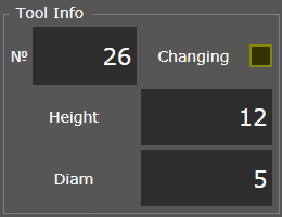
- Turn on standby mode (the "Changing" indicator flashes in yellow).
 All previous operations are performed automatically, receiving instructions from the macro.
 - Replacement of the cutting tool (milling cutter) - is carried out manually by the operator, subsequent measurements are optional.
- After replacing the tool, the operator needs to click the "Start" button in the PUMOTIX interface so that the macro terminates the program.
- Auto-correction of tool length (auto-testing). The procedure does not require additional moves, since the probing point is by default located at the tool change point.
- Turning on the spindle, restoring the initial state of the system.
- Starting further execution of G-Code.
Scenario 3: Automatic tool change (the macro template is the Auto).
Automatic tool change occurs sequentially according to the following algorithm of actions:
- Raising to a height SafeZ, if it has been set.
- Spindle shutdown.
- Moving to the tool change point.
To analyze further actions, look at the “Tool Table” window directly in the PUMOTIX program (“Configuration” → "Tool Table").

At the bottom of the window is the “Tool Change Mode” field, containing the selection and input of coordinates of the tool change point.
When you select "From the Tool table" for each of the tools added to the table, it becomes possible to enter individual shift coordinates. According to these coordinates, further actions take place that look as follows:
- Move to the cell of the current tool.
- Reset the current tool to a cell.
- Move to the cell of a new tool.
- Capture a new tool.
When selecting “Joint for all Tools”, a single change point is set, and the tool change itself contains the following steps:
- Moving to the shift point and reset the current tool.
- Capture a new tool.
In place of points 2, 4 and 6, the individual control logic is manually prescribed, based on the features of the apparatus for changing the tool, its connection and other conditions.
After capturing a new tool, the program automatically adjusts the height taking into account the “Length” parameter from the “Tool Table”, and then returns to the G-Code.
When using this scenario, user intervention is not required, all actions are performed as part of the control program.