Plasma Cutting Module Interface
The PUMOTIX program user interface "Plasma Cutting" is divided into tabs and consists of the following set of screens:
The “Workflow Process” screen is the main screen of the "Plasma Cutting" module. It contains buttons for loading, editing, executing and closing G-code, quick selection of a saved preset, cutting workflow control buttons, axis controls, THC signal indication, elements for jogging.
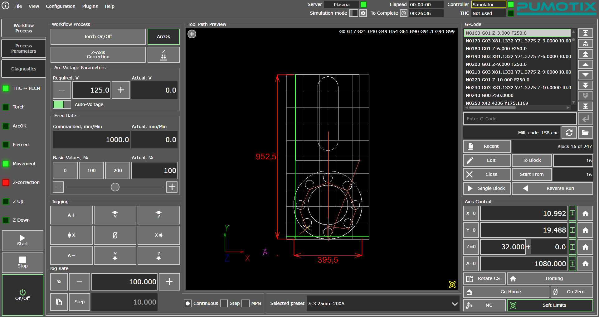
"Working Process" Tab interface
This tab is designed to control the operation of the machine while executing G-code. Path preview elements allow you to visually monitor the position of the cutter relative to the drawing, the progress and execution of the program. The tab allows you to quickly adjust the main parameters of a working machine: arc voltage and cutting speed (feed rate).
The "Process Parameters" tab is used to set cutting parameters depending on the material used. The cutting process parameters are logically divided into two large groups: parameters affecting tool movements and and parameters responsible for the process and quality of regulation of the torch height above the material. A more detailed description of each of the parameters is given in the Description of Plasma Cutting Parameters section.
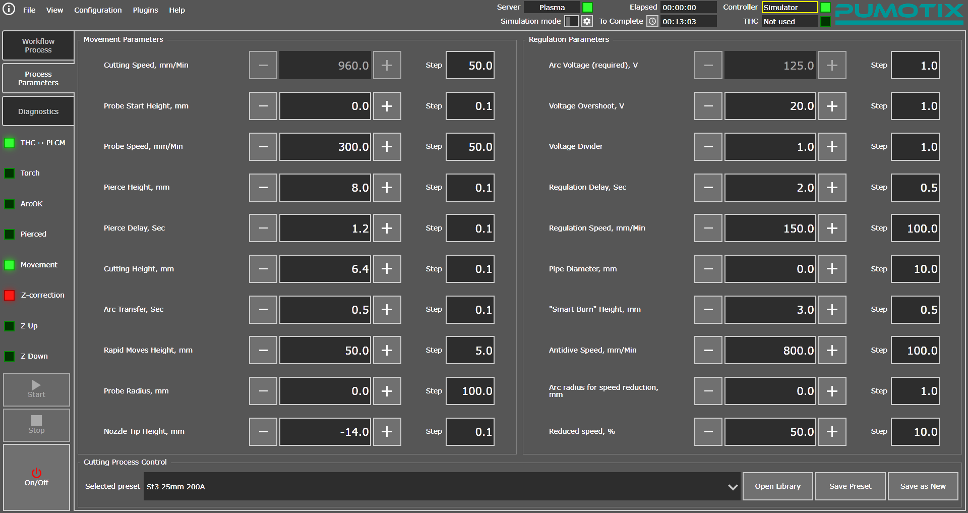
"Process Parameters" tab interface
This screen also allows you to work with the Plasma Cutting Parameters Library. A more detailed description of the library's operation is available in the Working With The Plasma Cutting Parameter Library section.
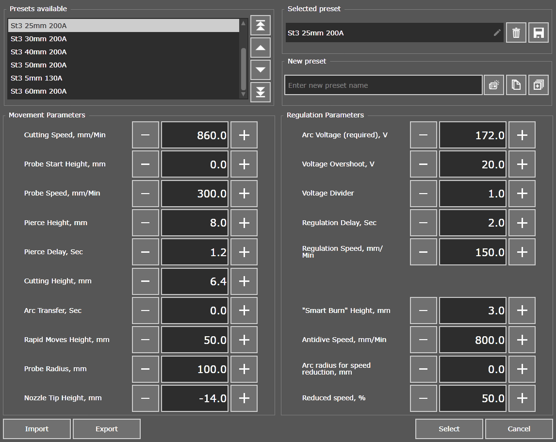
Plasma Cutting Parameters Library
The "Diagnostics" tab allows you to control the basic parameters of the machine, such as coordinates, input and output signals, motors signal states, THC regulation error flags and other.
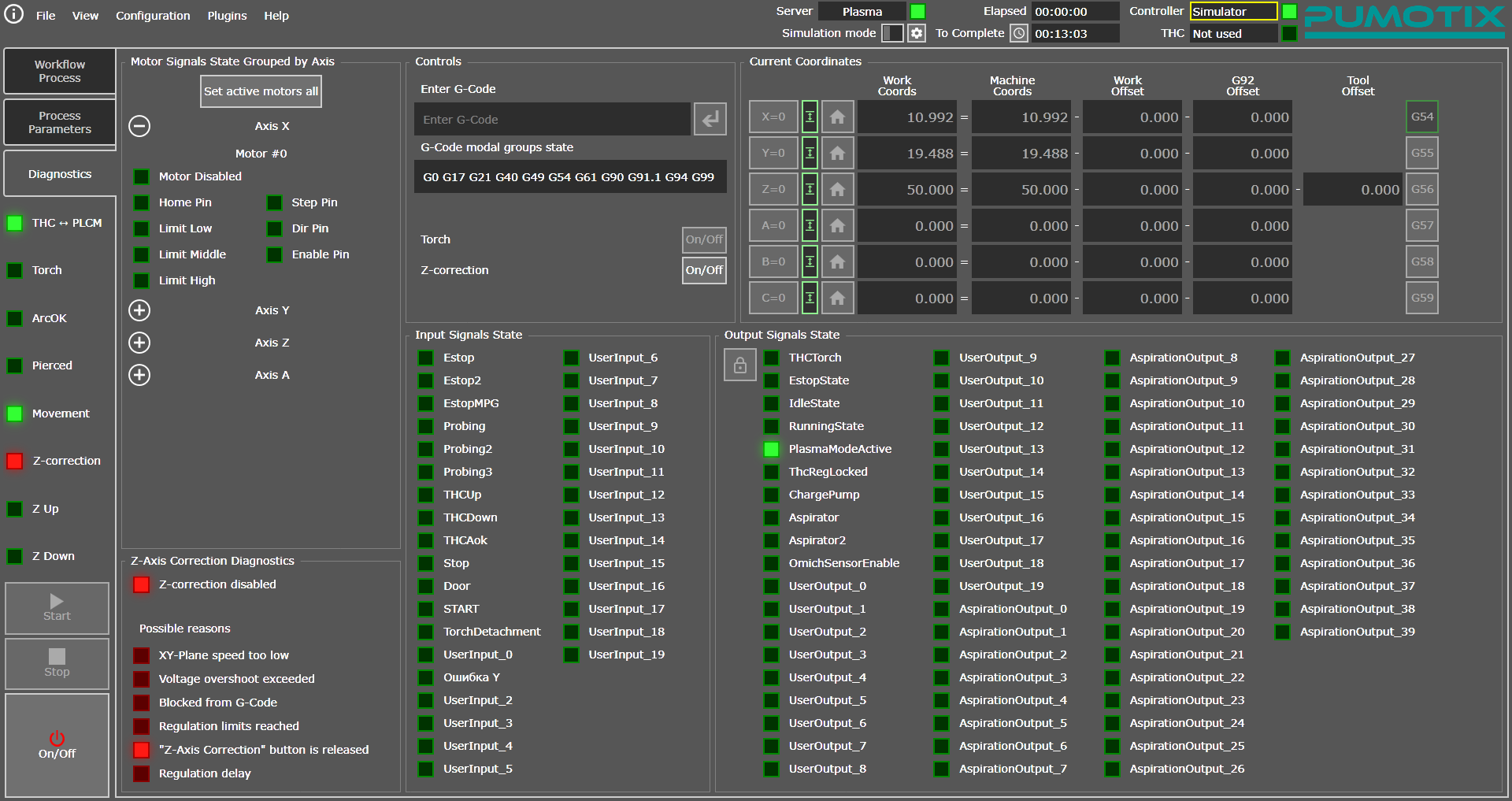
The "Diagnostics" tab interface
A set of elements on this page allows you to receive feedback from the machine, check the operating logic of the input and output signals of the system, monitor the Step/Dir/Enable control signals on each connected motor, and also determine the reason for the lack of THC cutter height control (more detailed diagnostics of control faults described below).
The following set of controls is common to all tabs of the "Plasma Cutting" module.
"On/Off", "Stop" and "Start" buttons allows to enable the machine, to stop or to start the NC program execution regardless of the selected screen.
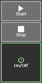
Main system control buttons
- "On/Off" button
Turns equipment on/off, sends an Enable signal to engine drivers, and unlocks all the functionality of the PUMOTIX program. This button also serves as the Emergency Stop or Estop button of the system in case of an emergency (accident) or a critical error in the system, which could entail danger to life and health of the operator of the CNC system, as well as to prevent damage of machine and equipment. - "Start" button
Starts NC program (G-code) loaded in PUMOTIX. Starting from the specified line is also carried out using this button. - "Stop" button
Stops the execution of the NC program or any other movements of the machine axes (for example, homing, probing, etc.).
Dashboard with selected PLCM and THC controllers
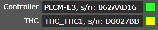
Controllers panel
The indicators to the right of the name of the selected controller display the current state of the network connection of the PUMOTIX program with this controller:
| controller not selected; |  |
| connecting; |  |
| connected. |  |
During normal operation, both indicators should be green. You need to check the network settings for controller which connection status indicator is yellow. This indicator state means that the controller has been selected in the PUMOTIX settings, but the program cannot establish a connection with it.
Indication of THC module operation signals

THC indication panel
This panel displays the status of special signals used to operate the THC altitude correction module. The panel contains 8 light indicators (LED):
- THC → PLCM
Displays the presence or absence of communication between the THC controller and the PLCM controller. In normal operation mode of the THC module, communication should be present, and the indicator will glow green. If there is no communication between the controllers, all THC functions will be disabled and cutting will proceed without regulation. To ensure communication, it is necessary that the THC and PLCM controllers be connected to a local network and have an IP address and mask from the same subnet. - Movement
An indicator indicating the possibility of moving the axes. This signal is in an inactive state at the moment of burning the material, as well as at the moment of absence of the ArcOk signal. Burning of material, as well as a missing ArcOk signal (with the ArcOk Wait function active), is a sign that axis movement is now prohibited. Movement will become available from the moment the burn duration ends or the ArcOk signal is detected. - ArcOk
Displays the status of the ArcOk input in the THC block. - Z-correction
It has three states:
| regulation is not used at the moment; | |
| regulation is used and works fine; | |
| regulation should be used, but is not currently available for some reasons. |  |
You can determine the reason for the lack of control on the Diagnostics tab in the Z-Axis Correction Diagnostics section. The figure below shows indicators of common causes of torch height not being adjusted. If there is an error, the LED lights up red.
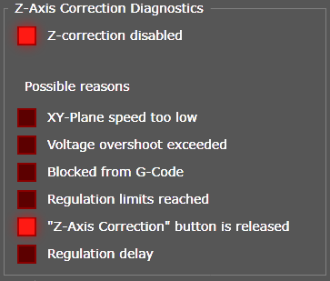
Z-correction diagnostics block
For more detailed information about a specific reason, you need to hover your mouse over the signal indicator icon:
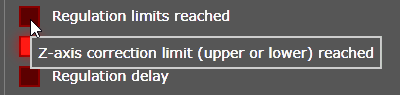
Description of the problem
- Torch
Duplicates the output state of Torch Fire. Lights up if the contacts are closed and does not light up if the contacts are open. - Pierced
Signals that burning of the material has been successfully completed, and you can begin moving the cutter along the contour of the part. - Z Up
Torch height correction signal up. - Z Down
Torch height correction signal down.