Setting Cutting Parameters
Working Process
PUMOTIX allows you to flexibly configure the entire set of plasma cutting process parameters. Some parameters can be changed dynamically. Часть параметров можно менять динамически, during the metal cutting process. The remaining parameters are applied before each new cutting contour (before M03/M04 macro).
Dynamically changing parameters
Directly while cutting the material PUMOTIX allows you to change the following set of parameters:
- arc voltage (required);
- voltage overshoot;
- regulation speed;
- antidive speed;
- min correction value;
- max correction value.
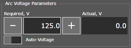
Voltage setting and monitoring
Also, during the process of NC execution, the operator has the ability to change the current cutting feed rate using the Feed Rate control on the main screen. Available change range: 0-200% of the desired feed rate.
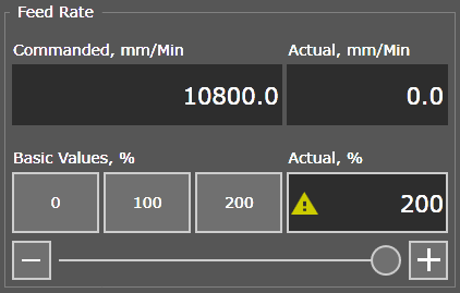
Feed rate installation and monitoring
A change in the “Commanded, units/min” parameter will be accepted before cutting the next contour (that is, before the next M03/M04 macro).
Other parameters
All remaining parameters are not dynamically changeable and are applied in the system before each burning:
- cutting speed;
- probe start height;
- probe speed;
- pierce height;
- pierce delay;
- cutting height;
- arc transfer;
- rapid moves height;
- probe radius;
- nozzle tip height;
- voltage divider;
- regulation delay;
- pipe diameter;
- "Smart Burn" height;
- arc radius for speed reduction;
- reduced speed (%).
These parameters can be set and changed both before launching the program for execution and during the execution of the program. PUMOTIX reads and applies the changed parameters before starting the next burn.
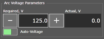
Auto-Voltage
The PUMOTIX plasma cutting control system allows you to use the automatic arc voltage capture function. This feature is useful if the machine operator does not know exactly what the desired voltage should be set to cut a given material, but knows the working height that must be maintained throughout the entire cutting process. Thus, with the “Auto-Voltage” feature active, the system will use the arc voltage that was established at the start of Z height adjustment. This voltage will be measured by the THC unit automatically and recorded in the “Required , V” parameter. When the "Z-Axis Correction" feature is enabled, the system will maintain the captured voltage until the end of the contour cut.
The feature is activated by the “Auto-Voltage” button or automatically if the “Required, V” parameter field is set to 0 volts.
Auto-Voltage
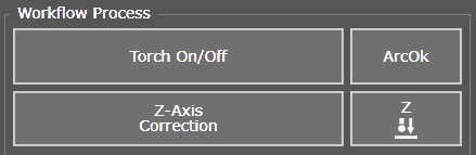
Workflow control buttons
On the main “Workflow Process” screen, in the “Workflow Process” group, there is also a set of buttons for controlling some plasma cutting functions:
Workflow control buttons
The “Torch On/Off” button is used to send the plasmatron torch on and off. When performing NC, as a rule, the torch is not turned on manually. The torch is turned on using М03/М04 macros directly from the NC. Turning on the plasma torch with a button is used when cutting metal in manual mode (moving axes using buttons from the screen or keyboard). To quickly turn on/off the torch from the keyboard, you can use the F5 hotkey.
An additional function for manual metal cutting is the function of copying the desired feed rate to the jog rate speed. When this function is activated, the system will automatically switch to the mode of manual movements with the copied feed rate. You just need to drive to the desired starting point for manual cutting, turn on “Z-Axis Correction” (if necessary), activate the Torch and cut the contour using the keyboard.
The “Copy desired feed” button is located on the main screen in the jogging control unit.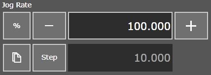
- The “ArcOk” button turns on/off the use of the ArcOk signal - the arc transfer signal. This signal forms the block of the plasma cutting apparatus (PCA) when the arc transfer is successful. When the "Wait for ArcOk" feature is enabled, PUMOTIX will execute the arc ignition command and enter ArcOk signal waiting mode. As soon as the signal is received from the plasma unit, PUMOTIX will continue to complete the ignition procedure and reach the working cutting height. If the ArcOk signal is lost during contour cutting (the arc goes out), the program execution will be interrupted.
When the "Wait for ArcOk" feature is disabled the PUMOTIX control system works with the parameter “Arc transfer duration” (see description of the parameter in the previous chapter). Disabling this option makes sense if the used APR does not have an ArcOk signal output. - The “Z-Axis Correction” button turns on/off the torch height above the material by holding the desired tension. Adjustment of the physical distance between the torch and the workpiece during cutting is carried out depending on the voltage of the plasma arc. The regulation mechanism is that the THC controller transmits the effective arc voltage via the Ethernet network. The CNC controller receives this information and makes height adjustments, after which it transmits the current adjustment status to PUMOTIX. Thus, the controller knows not only the required direction of correction, but also the amount of deviation from the nominal value, from which the required Z-axis displacement at a given time can be determined. This ensures high precision in maintaining the cutting height, which has a positive effect on dross-free cutting, cut appearance and dimensional stability of the part.
- The “Probing Z” button starts the probing algorithm for the surface of the material. The Probing sensor signal must first be configured in the section «Settings» → «IO» → «Input Signal Parameters».The metal surface will be searched, the Z coordinate will be reset and rise to a safe height (the value of the parameter “Rapid Moves Height”). If a signal from the sensor was not received at the end of the search for material, the system will display a corresponding message.
Simulation mode
The simulation mode allows you to perform a program without turning on the torch with a given feed and height.
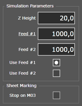
Simulation Mode parameters
When the “Stop on M03” feature is active, the simulation will pause at each burn point until the “Start” button is pressed. The cutter will be located above the piercing point. This mode can be used to manually mark cut-in points.