Description of Plasma Cutting Parameters
Movement Parameters:
- Cutting speed, units/Min
Required feed rate (cutting speed) in length units per minute. The value depends on the type of metal and the parameters of the equipment used. As a rule, the value of this parameter is set according to the cutting table given in the operator's manual of the equipment used. Set in units of movement (mm, inch, etc.) per minute. - Probe Start Height, units
The height above the material to which the cutter will quickly move down during the probing. Set in units of movement. - Probe Speed, units/Min
Workpiece probing speed along Z-axis in units per minute. - Pierce Height, units
Nozzle tip height above workpiece surface to fire plasma torch on. Set in units of movement. - Pierce Delay, Sec
Time delay in seconds given to plasma arc to burn through workpiece on the "Pierce Height". - Cutting Height, units
Height value (in current measurement units) to move cutter to after burn-through process completion. - Arc Transfer, Sec
This parameter is used to emulate arc transfer. If the system is not using the ArcOk signal, the system will perform the specified delay before moving. Set in seconds. - Rapid Moves Height, units
Height of the torch relative to the material during idle moves between contour cutting areas. Set in units of movement. Probe Radius, units
If the next ignition is carried out at a distance less than the probe radius from the location of the last probing, then the current Z coordinate is considered to be correct, and a repeated search is not required. Ignition will be carried out without searching for metal. If the value is zero, the probing will be performed before each ignition. Set in units of movement.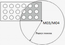
Probe Radius
Nozzle Tip Height, units
The value to assign to the Z coordinate immediately after probing. If the touch is made by a nozzle, then there should be a zero value. If another sensor is used, then at the moment the sensor is triggered, the nozzle is at a certain height from the metal, and this height depends on the installed nozzle. It is this height that should be indicated in this field. Set in the units of movement.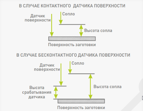
Correction for nozzle height when probing
Regulation Parameters:
- Arc Voltage (required), V
Required arc voltage value should be chosen in accordance with plasma source manufacturer's cut charts. If a zero value is specified as the required voltage, the system will automatically enter auto-voltage mode. Automatic voltage capture allows the THC controller to lock the current voltage in the arc after the regulation delay has expired and maintain it until the end of the cut. Set in volts. - Voltage Overshoot, V
Maximum actual voltage overshoot value at which Z-axis coordinate is still allowed to be adjusted towards workpiece surface.
When the arc crosses a gap or already cut path, the THC module detects a voltage spike and decides to lower the cutter down to stabilize the voltage near the desired one. This parameter allows you to set the magnitude of the voltage surge, if exceeded, the system will block the torch from lowering down to prevent the nozzle from colliding with the workpiece or structural parts of the machine. ПAt the same time, upward height adjustment remains available. As soon as the current voltage is within the overvoltage range, regulation is again available in both directions. Set in volts.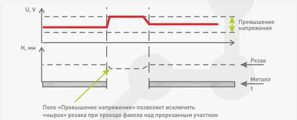
Voltage Overshoot
- Voltage Divider
Voltage divider is applied to LV-input only and defines division ratio for plasma source output voltage value. For example, if the THC is connected to the output of a Hypertherm source with a division ratio of 1:50, then the number 50 must be entered in this field. HV-input should have this value set to 1. - Regulation Delay, Sec
Delay for turning on the Z height correction after the torch reaches the working height. Immediately after moving to the working height, movement begins along the trajectory specified in the G-code, but at the beginning of the movement the voltage is not yet stabilized and, as a rule, is greatly overestimated. This parameter prohibits the movement of the Z axis for a specified time. The specified time should be sufficient to accelerate to rated speed. Set in seconds. - Regulation Speed, units/Min
Plasma cutter's Z-coordinate adjustment speed when "Z-axis correction" option is enabled. Too high a speed can cause skipping steps or overloading the servo driver. Otherwise, the system may not have time to monitor the curvature of the surface. The parameter depends on the degree of curvature of the material and the selected feed, therefore it is selected experimentally for each cutting mode. - Pipe Diameter, units
Defines pipe diameter for cutting using the rotary axis. Specifying the pipe diameter allows you to enable smoothing with simultaneous movement of the linear and rotary axes, and also interpret the feed as the speed of movement along the surface of the pipe. - "Smart Burn" Height, units
"Smart Burn" option increases nozzle tip height over workpiece surface during piercing stage to prevent possible damage from splashes of molten metal. The principle of operation of “Smart Burning” is based on the fact that the electric arc can noticeably lengthen if it has already been ignited, but the arc will not break. You need to move up to the burning site, lower yourself to the required height and turn on the plasma torch. As soon as the arc lights up stably and the plasma device turns on the ArcOK signal, you can slightly raise the plasma torch to a safer distance and wait for the burning to finish. After this, you can again lower yourself to the cutting height. By this moment, a hole has already appeared in the material, the plasmatron blows all the metal splashes down through it. To use the “Smart Burning” option, no additional configuration of PUMOTIX and G-code generation programs is required. The G-code remains the same. You just need to set the "Smart Burn" Height parameter in movement units (mm, inch, etc.). If this value is not zero, then immediately after the ArcOK signal appears, the controller raises the plasma torch to the specified height. At the same time, it also records the burning time, starting from the moment the ArcOK signal appears. If the pierce time runs out during lifting, lifting will stop and G-code execution will continue. An illustration of how the “Smart Burning” option works is presented below.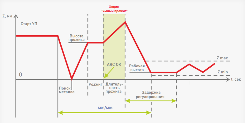
Scheme of operation of the "Smart Burning" option
- Antidive Speed, units/Min
Cutter's minimal speed along XY-coordinate plane to allow Z-coordinate adjustment (if Z-axis correction is enabled). When cornering, PUMOTIX slows down the movement of the torch, which leads to an increase in tension in the arc and, as a result, a possible lowering of the torch. To protect against this, a limitation has been introduced on the minimum speed of movement at which regulation will be carried out. If the current speed drops below this threshold, control will be disabled until the torch reaches speed again. The operation indicator of this option displays its current status on the THC signal panel. Set in the units of movement per minute. - Arc Radius for Speed Reduction, units
On arcs with a radius less than the specified one and a length greater than ¼ of a full circle, the cutting speed will be reduced. Set in the units of movement. - Reduced Speed, %
Percentage of the current cutting speed. The cutter will pass contours with small radii ad the speed.