Oxy-Fuel Cutting Module Interface
The PUMOTIX program interface “Oxy-Fuel Cutting (4 axes)” is divided into tabs and consists of the following set of screens:
The “Workflow Process” screen is the main screen of the module. Contains all the basic controls for the oxy-fuel cutting process.
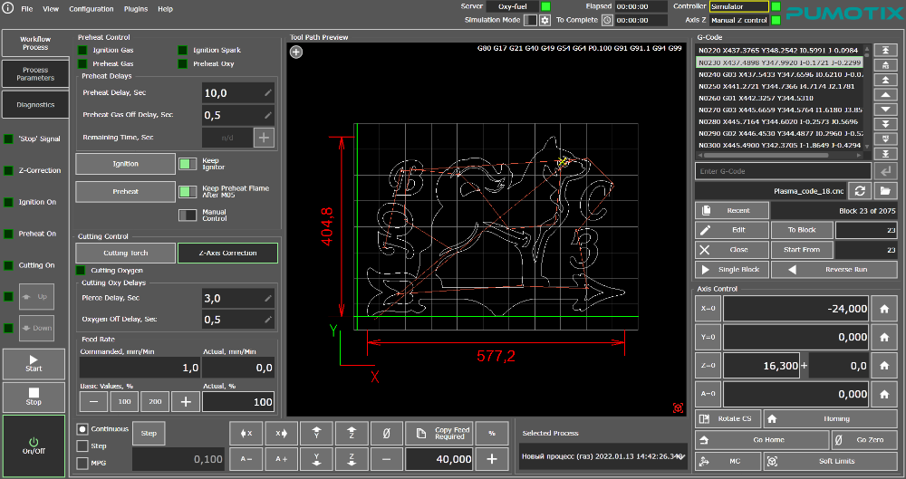
“Workflow Process” Tab
The screen provides the ability to prepare for the launch and start-up of G-Code, control the cutting process with the ability to adjust the basic parameters of the cut “on the fly”. From the main screen, the ignition of the gas burner, heating and cutting of metal are controlled, the working feed and the mode of manual movements of the machine axes are adjusted.
Trajectory preview elements enable visual control of the cutting position relative to the drawing of the program and the working area of the machine, flexible work with a shape cutting map (shift, rotation, scaling). The color scheme of the legend of the graphic window is available.
The controls for ignition, heating, and cutting are described in more detail below.
The “Process Parameters” screen is intended for setting and fine-tuning the cutting parameters. The tab consists of several groups of operating parameters and controls for gas cutting processes.

“Process Parameters” Tab
All the parameters of the oxy-fuel cutting process are divided into several types:
- gas valve opening/closing delays;
- parameters responsible for movements;
- parameters responsible for the correction of the torch height above the metal.
The tab presents the movement parameters and the correction parameters of the torch height (control parameters). A more detailed description of each of the parameters is given in the chapters “Displacement parameters” and “Regulation parameters”.
From this working screen of the program, access to the library of parameters for oxy-fuel cutting using the block "Preset Control".
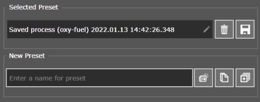
Oxy-fuel cutting process control unit
A description of the functionality of the parameter library can be found on the corresponding page.
The “Diagnostics” screen allows you to control the basic parameters of the machine, such as coordinates, input and output signals, and motor signals. The “Controls” block allows you to manually enter the G-code, evaluate the current status of the modal groups, test the operation of the burner ignition system, and start the heating and cutting torch. To debug the operation of the controller of the external autonomous axis Z, the control elements for the output of the correction signal (output “Capacity”) and the button “Z-Axis Correction” are used.
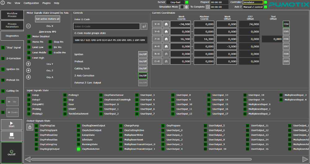
“Diagnostics” Tab
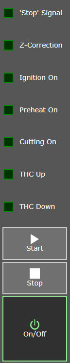 | The system control buttons, as well as the display panel of the main signals of the workflow are common interface components for all PUMOTIX tabs.
The workflow display panel displays the status of special signals of the Oxy-fuel cutting module, which allows you to visually control the current status of the system. The display panel includes the following signals:
|
- Z Correction
Displays the presence or absence of nozzle height correction above the metal. Gas cutting height control is carried out in three modes:
• external Z control;
• UP/DOWN protocol control;
• manual control of the Z axis.
The current mode is selected in the menu “Configuration” → “Settings” → “Oxy-Fuel” (more about the mechanisms for adjusting the torch height and Z axis control modes). - Ignition On
Displays information about the status of the automatic burner ignition system (if used). The indicator is active while the torch main burner is igniting (gas is being supplied to the ignition burner). - Preheat On
The indicator of the supply of heating gases to the torch. Active when there is a simultaneous supply of heating gas and oxygen, that is, the metal is heated before cutting. - Cutting On
Indicator of the supply of cutting (purge) oxygen to the torch. It turns on when the cutting oxygen valve is open. In this mode, metal cutting is carried out. - THC Up (UP)
Height correction indicator cutting up. In the autonomous axis mode or manual control, next to the indicator is a button for manual correction of the torch height up. - THC Down (DOWN)
Height correction indicator cutting down. In the autonomous axis mode or manual control, next to the indicator is a button for manual correction of the torch height down.